Using the non-standard Visual Editor
The Visual Editor is designed to help you alter your existing spring design to achieve the outputs you need. We're going to start with the simple dual-rate spring from the previous section:
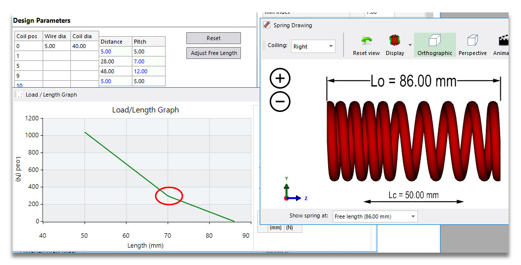
Let's say that we've got the right wire and outside diameters plus the right split of coils to give us the rates before and after the transition, but we aren't hitting the right loads at lengths. Click on the Visual Editor button on the toolbar, and we'll go interactive.
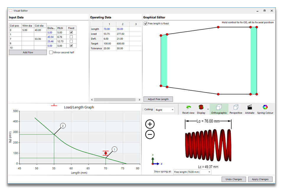
The Visual Editor is split into three inputs and two visual outputs. The inputs are the input grid, the operating data and the graphical editor.
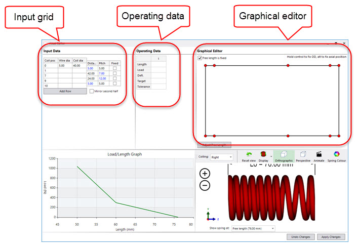
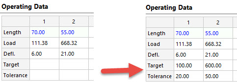
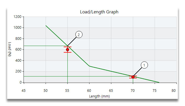
We can ignore the input grid for now, as it's almost the same as we've already seen on the Validation window. The operating data grid is also similar to those we've used before, but with one addition - as well as calculated values for the current design, we can enter target values and tolerances. Let's put some values in here, and specify working lengths of 70 and 55 mm. This gives the values on the left below. If we are trying to reach loads of 100 +/- 20 N and 600 +/- 50 N, we can enter those as our Target and Tolerance values:
These are shown on the load/length graph. You can see that the first one isn't too bad, but the second position is definitely out of tolerance:
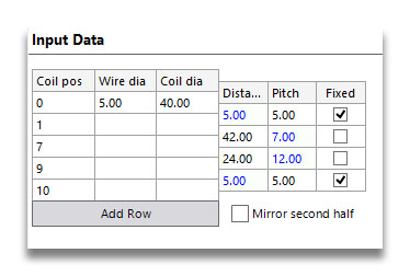
Now we're going to use the graphical editor to change the spring and try to meet those values as closely as possible. Before we make any changes though, we need to go back to the input grid. We're going to tick the top and bottom checkboxes in the Fixed column. What this does is tell the computer that the pitch in these two sections won't be altered as we adjust the rest of the spring. We need this to keep our closed ends. This is shown in the graphical editor as shading in those sections at either end.
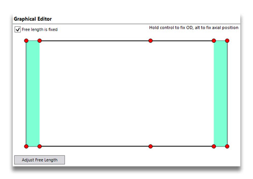
Now we're ready to redesign our spring. Drag the red handle at the top of the spring a little to the right. As you do that, you can see the load/length graph change. It should be quite easy to make it line up pretty closely with the target value.
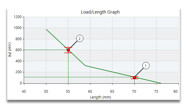
You may have noticed that you could only drag the handle in an axial direction. This is because there was no coil diameter entered at coil position 7. If you put a value of 40 in here, you would then be able to drag to change the OD at the centre of the spring as well as altering the pitch. Note that unless you also enter a 40 at coil position 9, the OD will expand at all positions after the one you drag:
Interference
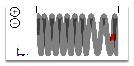
If you try to drag the spring around without fixing the ends, you'll increase the end coil pitch at one end and decrease it at the other. Given that both were exactly one wire diameter, this will immediately end up with a spring that can't physically exist. The interference (overlap of two consecutive coils) is highlighted in red as in the drawing below:
